

SMT PCBA employs small elements such as resistors, capacitors, and integrated circuits. The purpose is to help you. Read about pick-and-place machines, BGA, QFN packages, and solder paste. We will be talking about pads, vias, and tracks on boards. This is a guide on how to go about it when assembling PCBs.
What Is SMT PCBA And Why Is It Essential?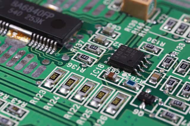
SMT PCBA involves using small parts such as resistors, capacitors, and integrated circuits. It accurately positions components on boards. SMT makes gadgets smoother and more effective. This method enhances reliability and minimizes size.
The layers of the board can have tracks, vias, and pads. They enhance electrical performance. Pick-and-place machines can place 30,000 parts within an hour. BGA and QFN packages are popular.
Solder paste joins parts to pads. After assembly, PCBs are submitted to AOI for inspection. This process ensures that every device works as it should.
How Does The SMT Assembly Line Work?
· Solder Paste Printing
The stencil printer applies paste on the PCB. This machine has laser-cut holes. It uses precise alignment. They ensure that the paste gets to the pads. The PCB assembly line stands in the frame of the printer. A squeegee applies paste through the stencil. Each pad gets solder. The process is fast.
It ensures accuracy. SMT PCBA requires this step. Paste thickness is critical. Stencil aperture size matters. The printer has pressure settings. Satisfactory printing leads to good bonding.
· Pick-and-Place
The pick-and-place machine places components on the PCB. This robot moves fast. It has a vacuum nozzle. It takes parts from feeders. It places them precisely. Every part has its place.
The machine checks alignment. It uses vision systems. Components are tiny. SMT PCBA assembly requires accuracy. The speed is high. This step is automated. Placement accuracy is vital.
· Reflow Soldering
The reflow oven melts the solder paste. The PCB enters on a conveyor. It heats up gradually. There are several zones. Temperature control is crucial. It has preheat, soak, and reflow phases.
Each stage is important. SMT PCBA uses reflow. This oven has accurate controls. The solder melts and makes the joints. Cool-down solidifies connections. The reflow profile is set. It ensures strong bonds.
· AOI Inspection
The AOI machine inspects PCBs. It employs cameras and lights. They detect defects fast. SMT PCBA quality relies on this. Each board is scanned. The machine identifies missing parts.
It checks solder joints. It applies algorithms. Inspection speed is high. This step is vital. The system alerts for errors. It guarantees that each board is flawless. AOI saves time.
· Rework Station
The rework station fixes errors. The technician employs a soldering iron. This station has tools. It repairs bad joints. The process is manual. SMT PCBA quality improves. Rework needs skill. The station has magnifiers. They ensure precision. Components are delicate.
It requires steady hands. The rework addresses placement problems. Assembly of electronic components is done. The station has air conditioning. Errors are corrected efficiently.
What Are The Key Components In SMT PCBA?
· Resistors
In SMT PCBA, resistors control the amount of current passing through circuits. They regulate voltage and safeguard the circuits. This tiny component has values like 100Ω or 1kΩ. Due to surface-mount technology, it can be assembled easily. Resistors differ in power ratings like 1/8W and are packaged in dimensions such as 0805 or 0603. They ensure circuits run safely.
· Capacitors
Capacitors store electrical energy in SMT PCBA and release it when necessary. Capacitance values range from 10μF to 100μF. Capacitors filter and smooth signals. Types include MLCC and tantalum. ESR is an important parameter. Capacitors can be 1206 or 0402 in size. They regulate voltages and enhance operation.
· ICs
PCBA with SMT manages multifunctional Integrated Circuits (ICs). They combine multiple parts into one chip, including microcontrollers, op-amps, and memory chips. IC packages like SOIC, QFN, or BGA exist, with pin counts between 8 and 100. They provide fast processing and data storage capabilities. ICs are crucial in current PCB assembly lines.
· Diodes
Diodes in SMT PCBA allow current to flow in one direction, preventing reverse voltage damage. Types include Schottky, Zener, and LED. An important parameter is their forward voltage drop, usually around 0.7V. Diodes provide protection and signal modulation. Small diode sizes like SOD-123 or SOT-23 are suitable for such applications.
· Transistors
Transistors in SMT PCBA act as electronic switches or signal amplifiers. Types include NPN, PNP, and MOSFET, which involve gain and switching speed. Packages such as SOT-223 or SC-70 accommodate various designs. Transistors control high power effectively and are used in amplifiers and digital circuits. They allow for small form factor and high-performance electronics.

How To Design For SMT PCBA?

· PCB Layout
SMT PCBA entails VCC and GND planes while designing. Locate ICs such as ATmega328 near decoupling capacitors. Route traces with a width of 6. Signal integrity is key.
Employ a via hole of 0.3 mm. They help connect layers, improving electrical performance and reducing noise. Assembly of electronic components ensures connections. Make sure there are at least 0.2 mm clearances between traces.
· Pad Design
For SMT PCBA, the pads should follow the IPC-7351 standard. Solder mask openings are critical. Ideally, each pad should have the same size as the component footprint.
Apply paste mask layers appropriately to prevent solder bridging. The aperture ratio influences the solder volume. It is essential for correct positioning of the components, ensuring reliability and enhanced thermal regulation.
· Trace Width
In SMT PCBA, current density depends on the width of the conductor. Thicker conductors carry more current. The formula for width is I=k*W^n.
To select the right trace width, assign a value of 0.7 to n. It reduces resistance and ensures efficient power delivery. They optimize performance. Avoiding overheating is essential.
· Component Spacing
Spacing is critical in SMT PCBA. Set components with a distance of 0.5 mm. It helps in reflow soldering and prevents tombstoning. Capacitors and resistors should not touch each other.
Use EDA tools for accurate placement. They enhance manufacturability. Check the DFM guidelines. Correct spacing prevents electrical shorts and allows easy inspection and testing.
· Thermal Relief
Thermal relief is desirable in SMT PCBA. Apply thermal pads on power layers. This helps in heat dissipation. Join pads to planes by spokes to reduce thermal stress.
This ensures stable soldering. Areas with large copper may require thermal vias. They transfer heat efficiently. Good heat dissipation prevents component failure. PCB assembly line ensures reliability.
What Equipment Is Needed For SMT PCBA?
· Stencil Printer
This applies solder paste on PCBs. The alignment accuracy of the stencil printer is 0.01 mm. Squeegee pressure ranges from 2 to 15. They use stencils made of stainless steel or nickel.
The thickness of the solder paste is between 0.08 to 0.2 mm. It helps in covering the surface evenly with the paste. Many types of apertures are possible. Speed control is essential. The cleaning system helps to wash off excess paste.
· Pick-and-Place Machine
Placement machines put components on PCBs. The accuracy is 0.005 mm. They can accommodate up to 10,000 parts. The placement speed is 15 per second. It employs vision systems for alignment.
Different components require different nozzles. It can handle thickness from 0.2 mm to 50 mm. Programming makes provisions for flexibility. Transporters contain parts that are to be inserted.
· Reflow Oven
Reflow ovens solder the components onto PCBs. Temperature zones vary from 120 to 240. The heating rate is controllable. It employs forced air or nitrogen. Conveyor speed ranges between 20 and 100.
There are six to ten zones in the soldering process. Strict control of temperature leads to the preparation of quality solder joints. Varying solder pastes are right for different profiles. The PCB assembly line has a cooling system that hardens the solder.
· Inspection Systems
Inspection systems inspect the PCBs for flaws. They employ the use of Automated Optical Inspection (AOI). The resolution is 10 µm. They can scan up to 50,000 parts.
It identifies misalignment; solder bridges, and missing parts. Different lighting directions enhance the detection. This system involves the use of 3D imaging for the depth dimension. Software highlights errors. Review stations permit manual examination.
· Solder Paste Mixer
Solder paste mixers prepare the paste for printing. They have a mixing speed of 300 rpm. The capacity varies from 500 to 1000 grams. This helps in achieving a uniform paste texture.
Different mixing modes are offered. This equipment helps in minimizing air bubbles. Timers regulate the mixing time. A balance is very important when it comes to printing. The design of the chamber also eliminates the risk of contamination.
· Rework Station
Rework stations repair faulty PCBs. They have a temperature range of 100 to 400 degrees. The airflow is adjustable. It consists of soldering and desoldering equipment.
This station is suitable for BGA, SMD, and other components. The solder is removed by the vacuum system. Some tips are general, while others are specific to different parts. Precise controls ensure accuracy. The assembly of electronic components is comfortable for the user.
How To Ensure Quality In SMT PCBA?

· AOI
This machine checks SMT PCBA quality. It uses cameras and lights to diagnose problems. AOI can distinguish between resistors, capacitors, integrated circuits, and diodes. It processes two hundred thousand parts per hour. Systems use 12MP sensors. The device analyzes the placements, soldering, and polarity of the units. This step helps to spot mistakes early. LHD Technology is the ideal partner for all your reliable PCB needs. This is why a good PCBA depends on AOI.
· X-ray Inspection
Inside, SMT PCBA gets checked with X-rays. It reveals hidden issues. They inspect BGA, QFN, and fine-pitch the solder joints. X-ray machines detect voids and shorts. This method identifies gaps as small as 0.05mm. It processes 150,000 parts per hour. High-resolution, 5µm, captures details. They find internal cracks. X-ray ensures reliable assemblies. LHD Technology ensures that all the products meet customer standards.
· Solder Joint Analysis
SMT PCBA has joints that need checking. This uses microscopes and software. It examines cracks, voids, and bridges. Observations for the analysis are done under the microscope at 400X magnification on joints. They are made with an accuracy of 0.01mm. They explore BGA and QFN interfaces. Joint integrity is checked through non-destructive testing. This process ensures that the solder connection is good. LHD Technology provides very accurate and stable assemblies.
· Process Control
The manufacturing of SMT PCBA needs to be controlled. Temperature and pressure, for example, are controlled by machines. They watch how the stencil is printed, placed, and reflowed. Process control ensures that all the parts are nearly equal to 0.02mm. The system constantly records data. It signals if the value goes beyond the given limit. Stability guarantees high returns. Process stability is key. LHD Technology applies rigorous measures of control to achieve maximum results.
· In-Circuit Testing
SMT PCBA is tested by ICT. It uses probes and fixtures. It monitors signals, voltages, and currents. ICT negotiates 1,000 points for each board. It identifies shorts, opens, and defective parts. It measures resistance, capacitance, and inductance with high precision. Automated scripts make it possible to run tests faster. This step ensures that boards are effective. At LHD Technology, comprehensive testing guarantees the best performance.
What Challenges Are Common In SMT PCBA And How To Overcome Them?
· Solder Bridging
Solder bridging can cause short circuits in ICs, BGAs, and QFPs. Use 0.1 mm stencils to help. Ensure correct paste deposition on pads. Position parts accurately with an X-Y robot. Check boards with AOI for errors. Set reflow profiles to 220°C. Monitor solder paste viscosity. Use no-clean flux to minimize residues. Test circuits with ICT. Keep humidity under 50%. Use ESD mats to handle static-sensitive devices.
· Tombstoning
Tombstoning lifts parts like 0805 and 1206 resistors due to uneven heating. Preheat boards to 150°C. Ensure consistent stencil apertures. Check for lifted pads with an X-ray. Apply solder paste evenly. Use low-residue flux. Solder at 230°C for 40 seconds. Maintain solder paste viscosity. Double-check component placement with SPI. Clean boards with IPA after soldering. Control humidity levels.
· Component Shifting
Component shifting moves SMD parts during reflow soldering. Use the paste with high tackiness. Check orientation relative to pick-and-place. Minimize conveyor vibrations. Look for trends with AOI. Verify reflow profiles at 225°C. Control paste viscosity regularly. Use high-resolution cameras for placement. Run functional tests after reflow. Clean with deionized water. Ensure stable temperature profiles during assembly.
· Solder Voiding
Solder voiding forms air pockets, compromising QFNs and LGAs. Apply paste uniformly. Inspect deposition with SPI. Use vacuum reflow ovens. Set profiles to 245°C. Check for voids with an X-ray. Ensure consistent stencil thickness. Use nitrogen for reflow soldering. Tightly control paste viscosity. Apply no-clean flux. Evaluate boards with functional tests. Clean with ultrasonic cleaners.
How To Optimize Your SMT PCBA Process?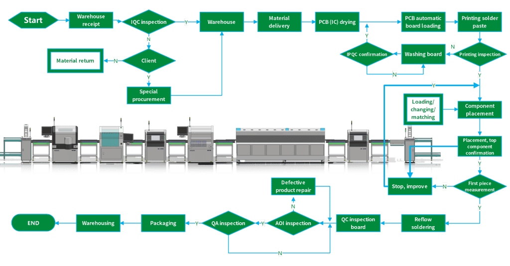
· Cycle Time Reduction
Short SMT PCBA cycles increase productivity. Reduce the conveyor speed to 0.2 m/s. The stencil apertures should be set at 0.3 mm, while P&P machines ensure proper part placement. Minimize rework by positioning BGA correctly. Apply Type 4 solder paste. Change the reflow oven temperature to 250°C. This speeds up production. Inspect solder joints with AOI systems to ensure quality. Maintain machines regularly. For parts, use nozzles such as 0402.
· Lean Manufacturing
Lean helps SMT PCBA. Reduce WIP to 100. Simplify component sizes such as 0603. This simplifies setups. Standardize P&P speeds to 0.1 m/s. SMED is most suitable for making fast changes. They cut times. Examine stencils with a 10x magnifying glass. Proper material handling is cost-effective. Use feeders with quick-change. Apply 5S to keep it tidy. Takt time should be controlled at 15 seconds. Balance workload. Use poka-yoke for errors.
· Process Parameters
Fine-tune SMT PCBA settings. Manage reflow oven zones at 150°C, 180°C, and 250°C. Change the soak to 60 seconds. Solder paste viscosity at 5000 cP is important. It affects prints. Adjust screen tension to 25 N/cm. Verify component placement to 0.1 mm. This ensures good work. The right P&P force should be 10g, while conveyor speeds must be set to 0.2 m/s. Preheat zones should be set at 150°C. Inspect boards after reflow. Calibrate tools often.
· Continuous Improvement
Always improve SMT PCBA. AOI data must be analyzed to identify defects, which are at 5%. Use feedback loops to raise yields. Apply PDCA cycles to refine steps. Experiment with new solder pastes such as SAC305. Assess stencil thickness of 0.3 mm. Improve P&P processes. Check reflow profiles at 250°C. Train staff regularly. Work as a team. Check performance often. This guides improvements. Innovate always.
Conclusion
SMT PCBA comprises parts such as BGA, resistors, and capacitors. Techniques such as AOI and reflow soldering help maintain quality. It is important to understand some parts, like solder paste and vias. For more information, please visit HD-PCB. Step up your PCB skills and increase efficiency!