PCB
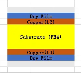
Printed Circuit board. This term is usually applied to the completed product consisting a fiberglass core with copper traces n spaces on the outer surfaces.
Trace and Space
The pattern applied to the layers of a PCB. Trace and space widths come from the design software and are contained in the “Gerber File” to the fabricator. They are usually designated by a thickness (in mils) of the trace followed by the thickness of the isolating space between the traces. For example, 5/6 refers to a 5-mil trace and a 6-mil space.
Core
A thin piece of fiberglass laminate with copper cladding on both sides. The core has fully cured epoxy and is intended to be buried within a multi-layer PCB structure. It is available in a wide range of thicknesses and of copper foil weights.

Photo Mask
A photosensitive material applied to the copper foil of the core or the outer layers of a PCB to allow the transfer (photographically) of the computer-generated (CAD) image in the Gerber file to the copper surface of the core or outer layer of the PCB
Etching
A process of removing a base layer of copper leaving only the desired traces n’ spaces. The etching solution is masked from the traces n’ spaces by a photo mask such that only the exposed base layer of copper is etched. This process continues to the surface of the laminate until all the traces n’ spaces are unsorted and there is no residual copper left between the traces.
Layup
The process in a multi-layer PCB where the cores are sandwiched between layers of glass Matt saturated with an uncured epoxy. The layers provide the insulating material between copper layers of traces n’ spaces, and they also provide the “glue” that bonds the inner layers together.
Prep reg
Thin sheets of a woven glass Matt that are saturated with a “B-stage” epoxy that is dry to the touch but uncured. When exposed to temperatures above the melting point of the epoxy, the B-stage flows around the copper circuitry (above and below) removing any air, filling all geometry, and bonding the surfaces together as it cures.
Prep reg is available in a wide variety of thickness due to the size and type of glass used to weave the Matt. The variety is further expanded by the types of epoxy resin saturating the Matt. The resin varies depending upon the amount of flow that is desired when the epoxy is liquid.
1-Oz Copper
The copper foil used by a fabricator is sold to them by weight. The weight is based on a uniform film of copper spread over 1 ft2 of surface. If 1 ounce of copper is uniformly spread over the 1 ft2, the thickness of the resulting copper is 1.4 mils (.0014) thick.
NOTE: A customer request for “1 ounce copper” on the surface is due to a misunderstanding of how the term is actually applied. While the fabricator does purchase the copper foil by weight, (1 oz, 2 oz, etc.) once the fabrication process begins, this designation is no longer correct. The purchased foil is either eroded chemically and mechanically or increased by plating (electron or electrolysis). Fabricators ignore this customer misapplication of the terms and instead defer to the IPC–A-600 definition: “thickness after processing”, which re-defines ounces into a thickness of copper (For example, 2 Oz is defined after processing as being 2.2 mils instead of 2.8 mils.)
Brick
This is a fabricator term for the double-sided, copper-clad structure that comes out of a laminating press once the core, prep reg, and copper foil have all been pressed together and the epoxy has cured. To the untrained eye, the “brick” looks like a piece of double-sided, copper-clad laminate.
Sequential lamination
Sequential lamination refers to a repetition of the lamination process. If sequential lamination is employed, its purpose is to create an “intermediate brick” that is intended to be used for additional processes. In sequential lamination, multiple intermediate bricks or a combination of intermediate bricks and double-sided cores are bonded together. This process can be repeated multiple times depending upon the process capability of the fabrication shop. The typical number of lamination is 3, but a few very specialized shops can perform 5–6. These are rare.
Welcome to visit our Basic process description for MLB and DSB


